|
VMC controller
|
|
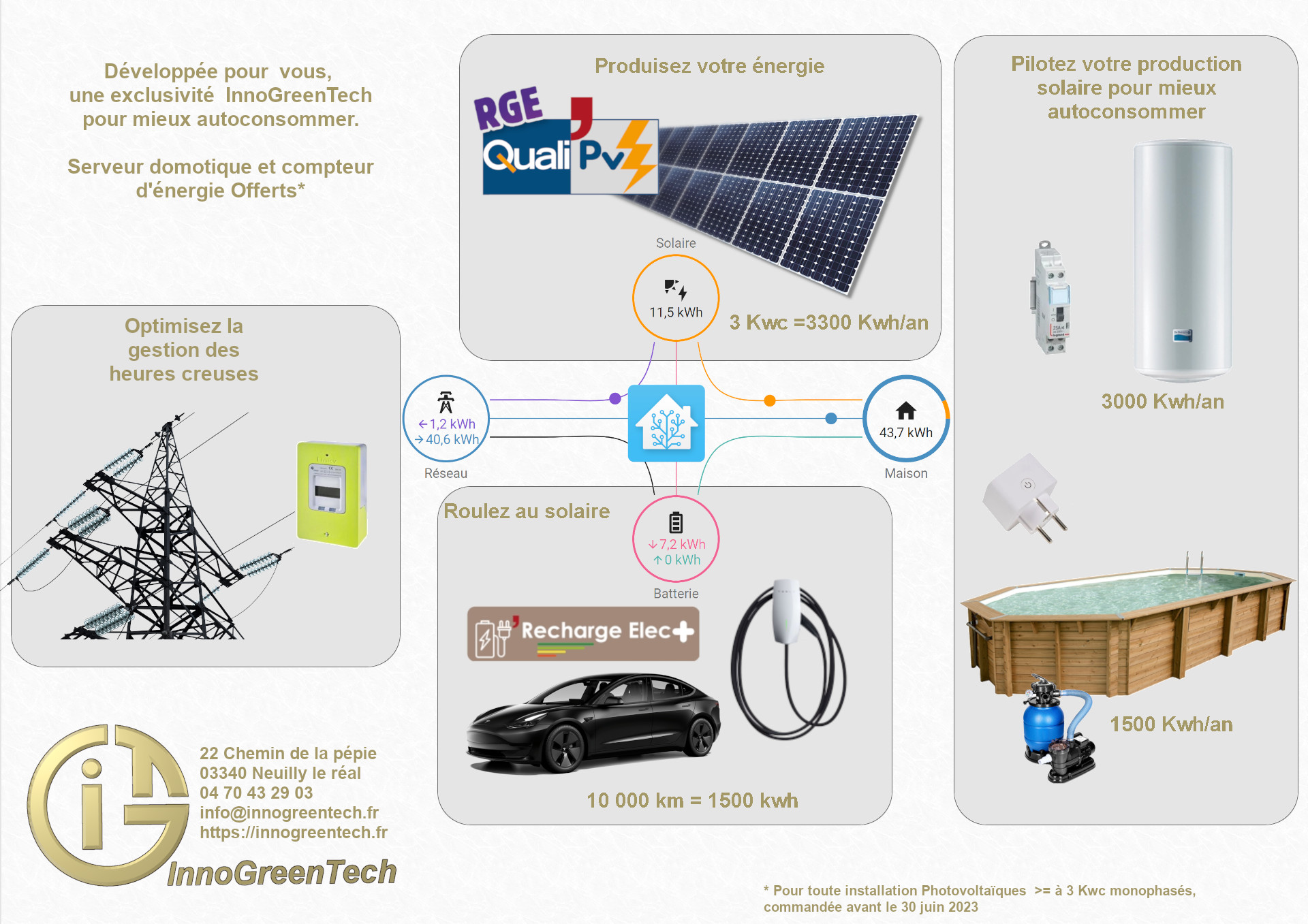
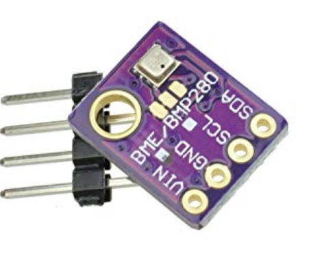
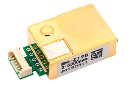
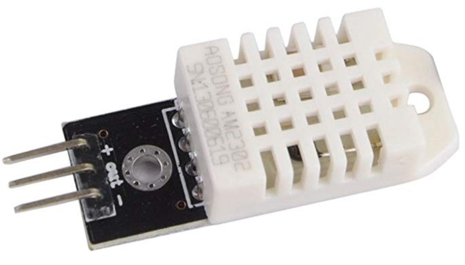
Here we are going to make a VMC controller. This objet allow to adjust the speed fan of a VMC. This speed will be set by the amount of CO2 in the air, the temperature and the humidity. The user can choice different modes of work. Outside the level CO2 is about 404 ppm, in your home it need to be under 1000 ppm. I have set my home at 700 ppm. The comfort level of humidity is about 40 %. Generaly the humidity in the house is higher summer than winter. it is because there is a big gap between outside and inside temperature. When your home will be empty the controller will decrease the fan becaus the CO2 will be down, in contrast it will increase when it will be full. It will be able to optimize in terms of your choice of mode. Winter to preserve the hot and summer to cooling the home. help to safe energy. For this the controller measure the level of CO2, the temperature and the humidity of the air in pipe. A outdoor probe allow to measure the temperature, the humidity and the pressure. With them it is possible to read every information on a touch screen and to do a forecast weather. The HMI is connected by a radio at the VMC board. It can be connected too at a modul to measur power consomation. Like this it is possible to have in real time the power that your home use.
A optionnal Wifi modul allow to acces at the data by a integrated web page. It is possible also to send a json file at a data base. At the end of this article, there is a link for access at every information on my Github account. In this video i explain how to use this object ( it is in french, sorry): |
|
Summary
|
|
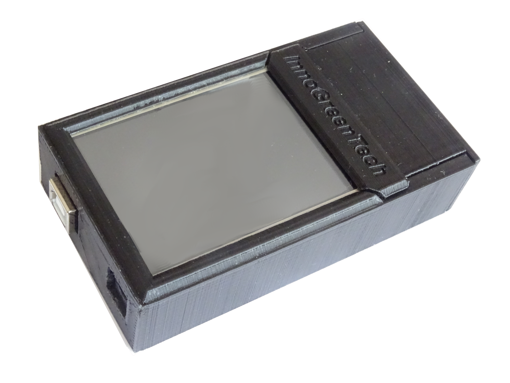
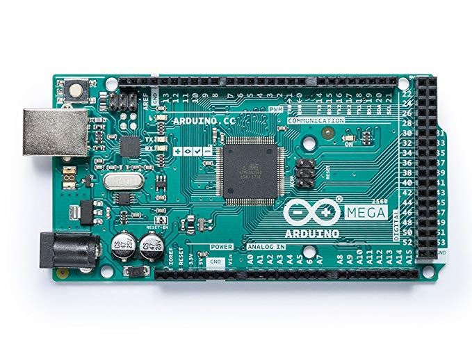
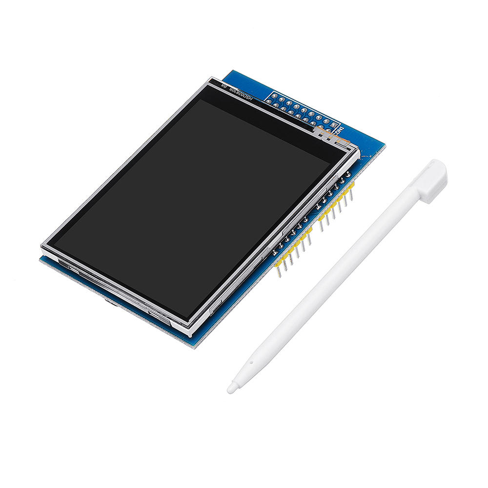
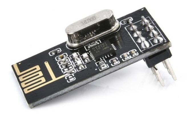
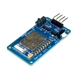
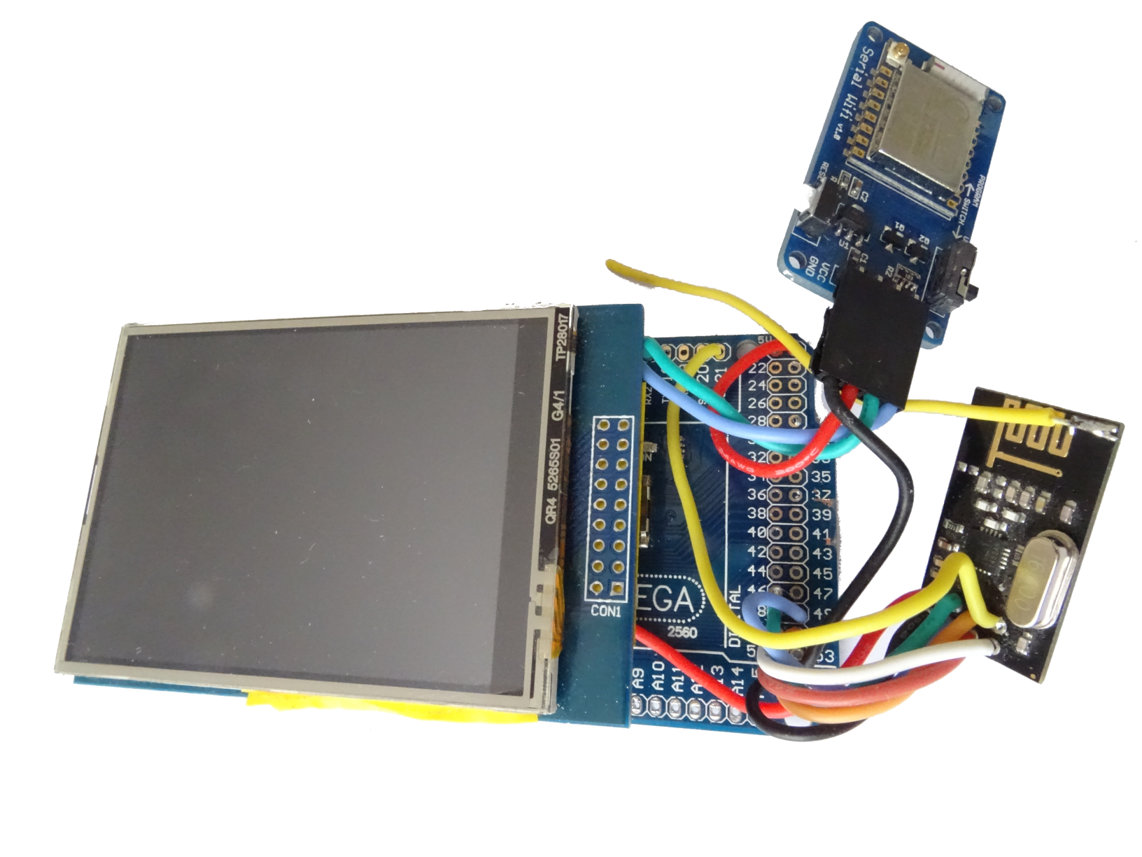
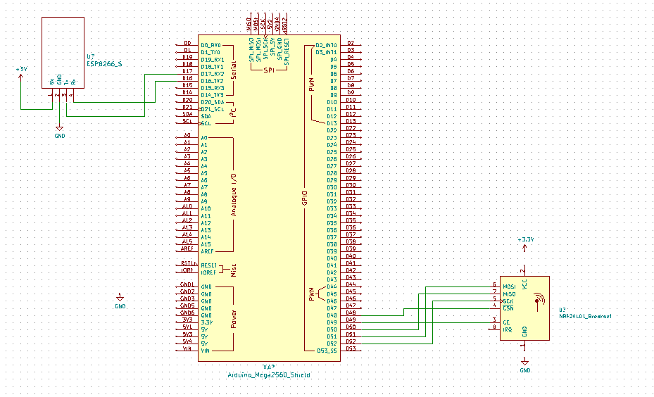
As HMI i have choice a Arduino méga with a 2,8" touch screen. A NRF24L01 allow to communicate with the VMC board and the modul of power measure. A optional ESP8266 allow to connect it on WIFI and to catch the data on a web page.
|
|
Assembly and drawing
To make this assembly, i have tried to reduce the dimentioning. It is for this that i don't use PCB, i have used silicon wire to do the wiring. It is necassary to keep the connector of the ESP8266 to can download the software. After the first compilation it will be able to update it by webpage.
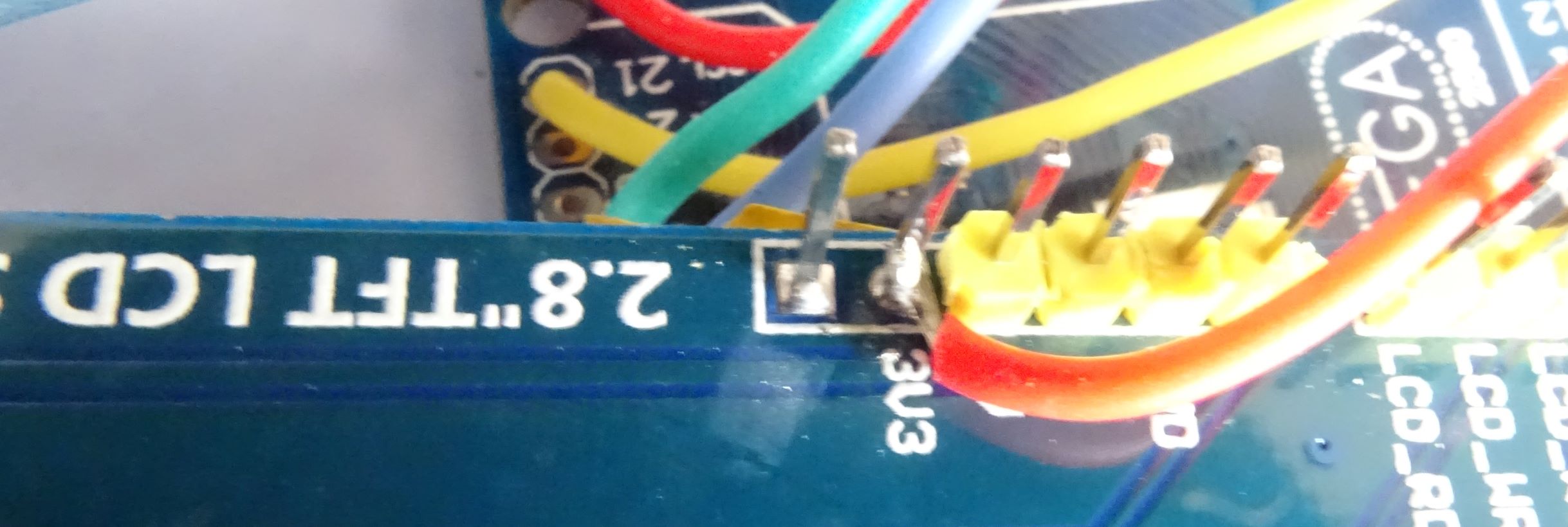
To solder a wire on 3.3 V i have released the insolation on the pin of the shield.
Follow this link to found the last drawing: https://github.com/InnoGreenTech
|
|
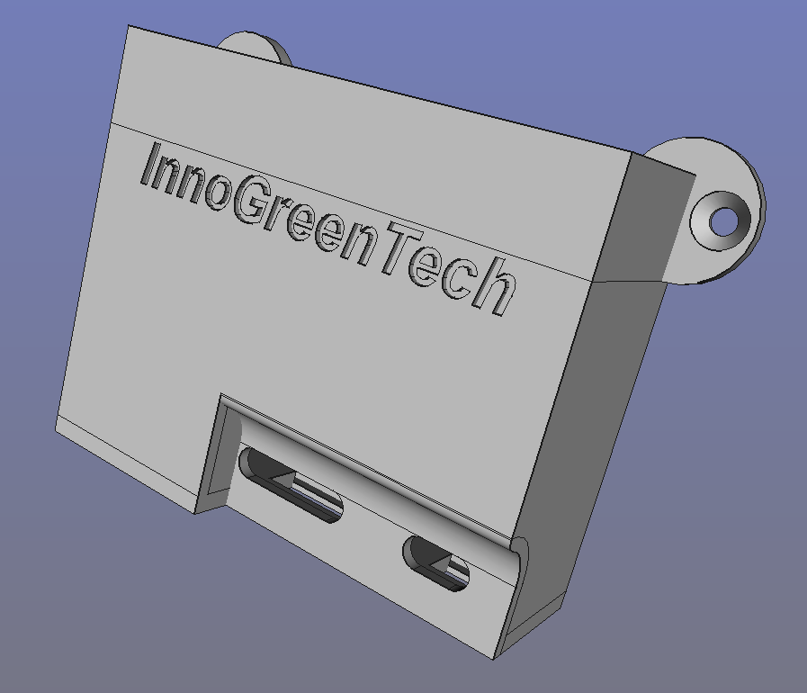
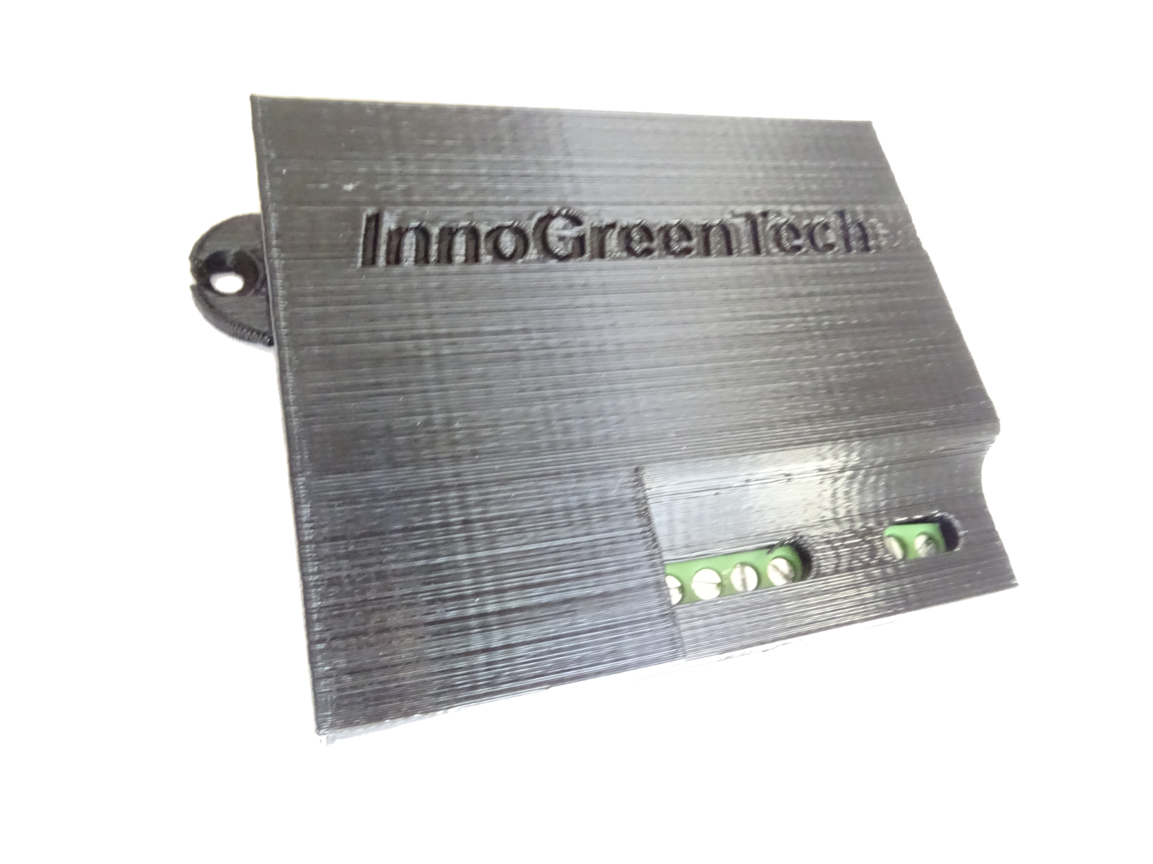
Box for the HMI
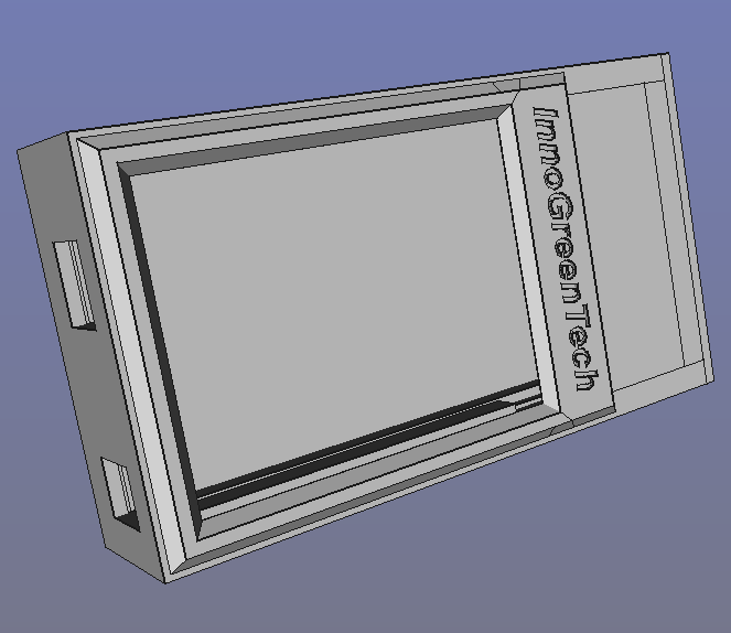
The box is made with a 3D printer in PLA material. The board is slided in the box, a plug comes to close the box. The STL files are also here: https://github.com/InnoGreenTech
|
|
Parts list for the VMC board
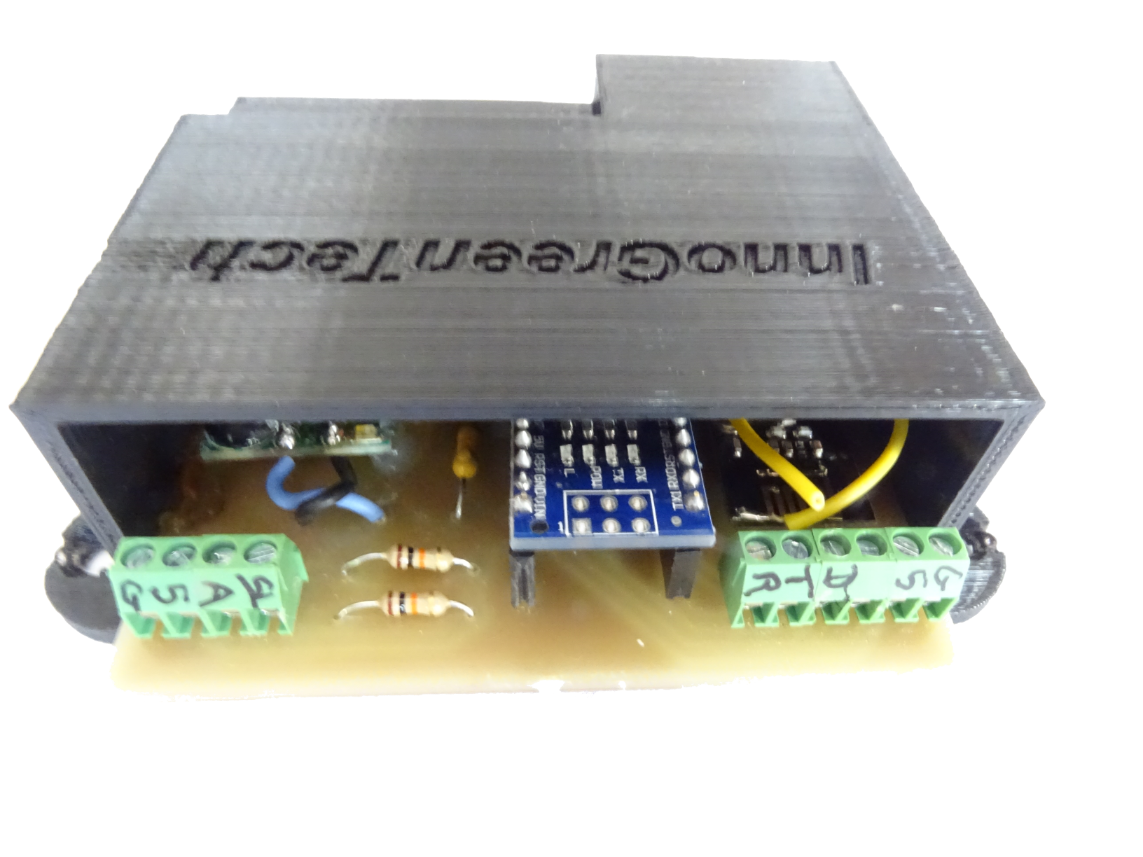
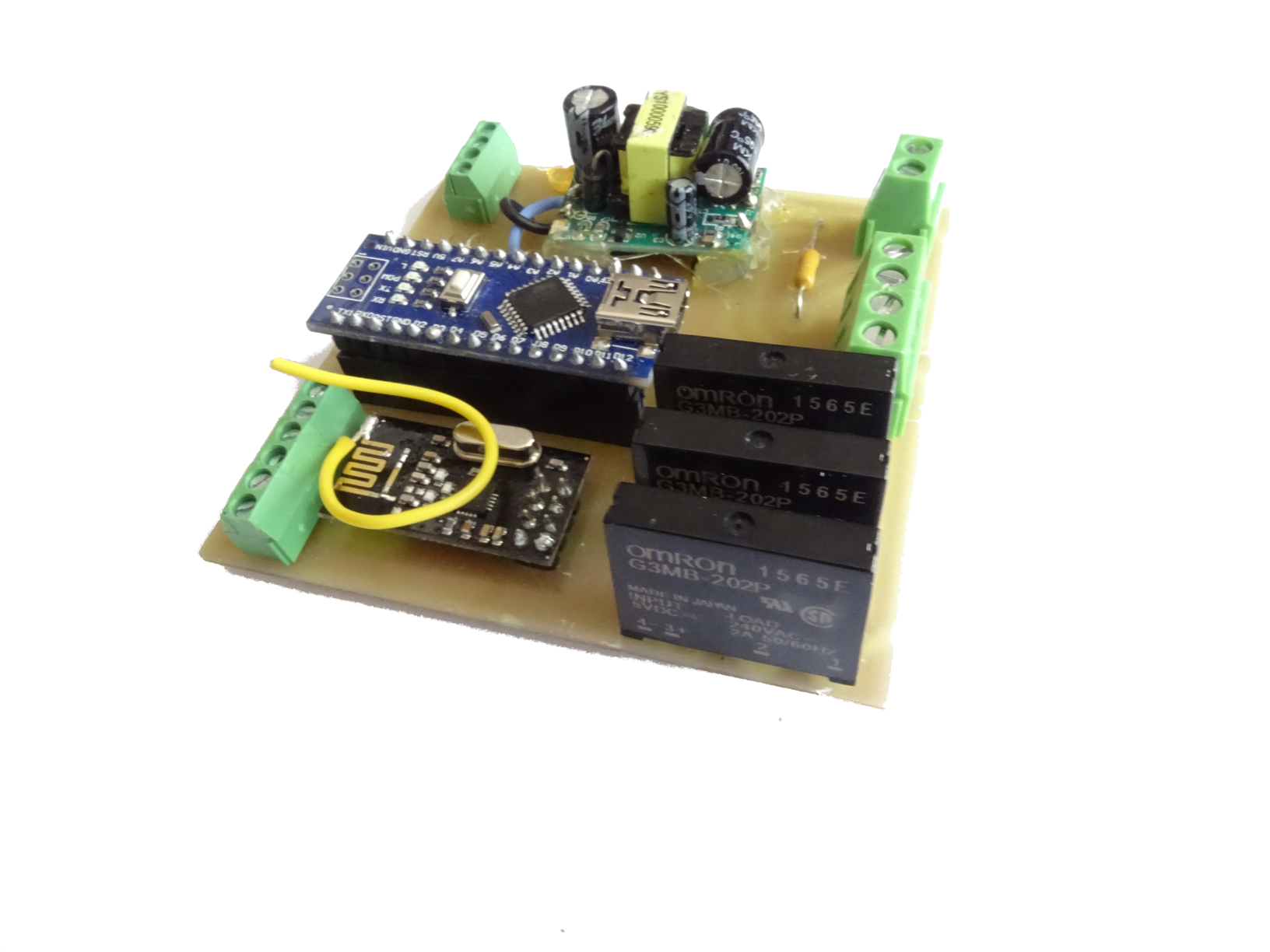
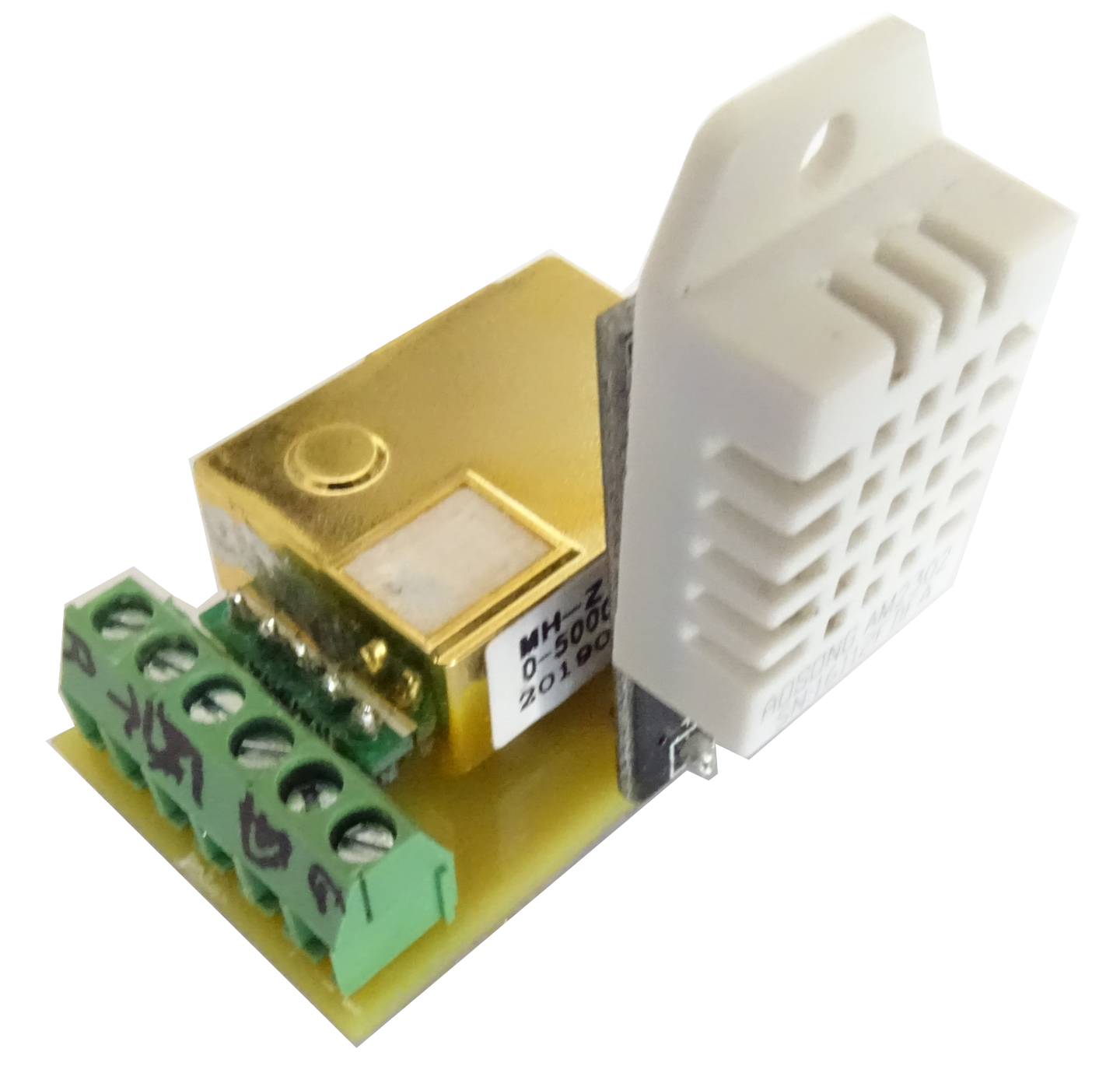
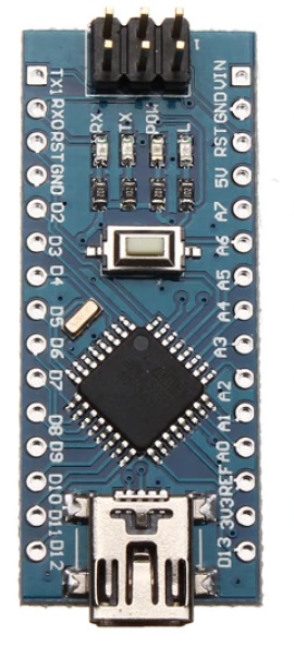
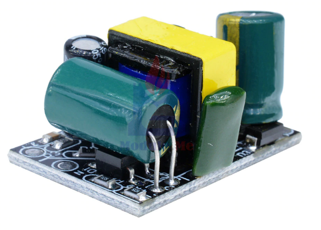
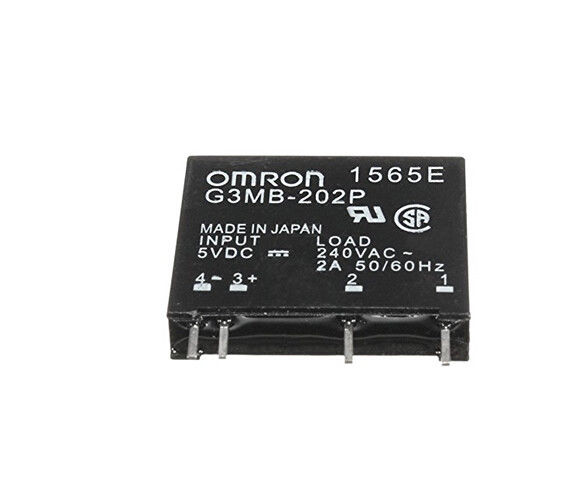
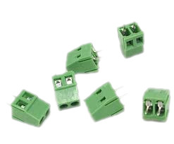
To assembly the VMC Board i have used a PCB . On it, there are a power module, a Arduino nano and 3 solid state realys. The 230 volts screw terminals are protected to have IP2x protection. There is also a PCB for the probes detinate for the pipe.
Parts list:
|
|
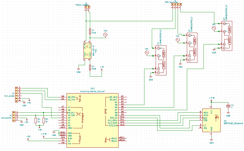
PCB et drawings for the VMC board
I have made drawings and PCB with Kicad software. To do the PCB i use English engraving with a CNC. For more informatio, you can watch this video, it is in French: https://www.youtube.com/watch?v=TDLYcnVbY08&t=312s To acces at every files you ca go to my account Github, i update files only here. https://github.com/InnoGreenTech, you will found another projects. Drawing VMC board:
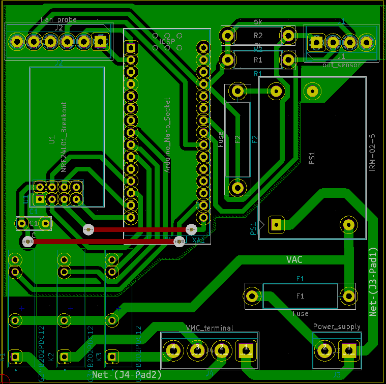
PCB VMC Board:
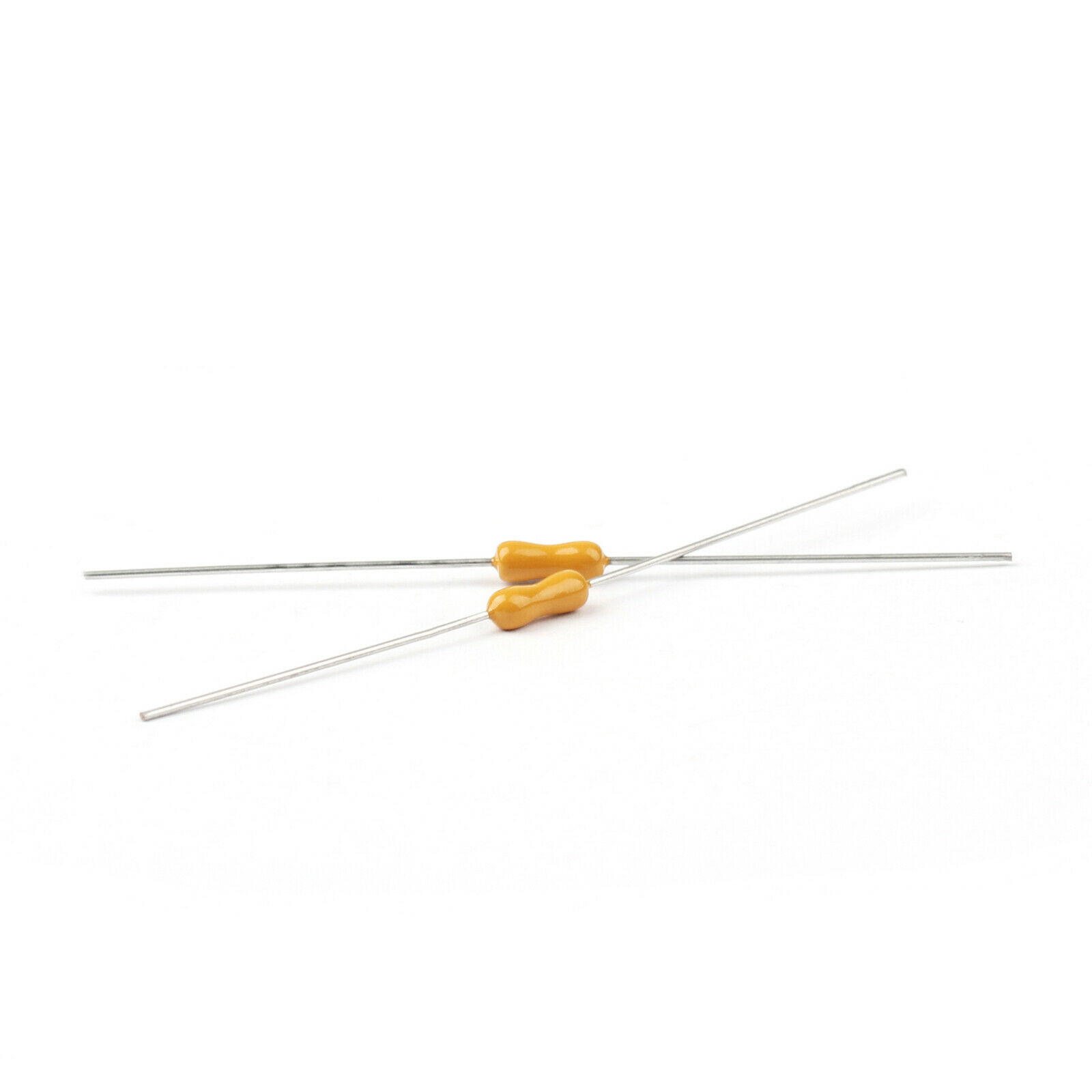
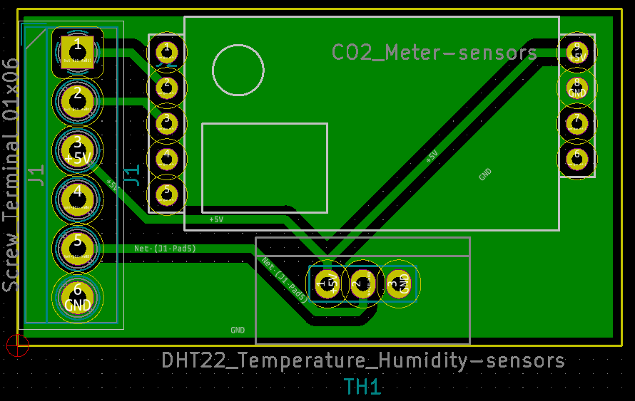
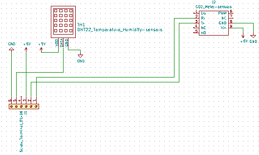
Probe drawing
PCB of probe:
 |
|
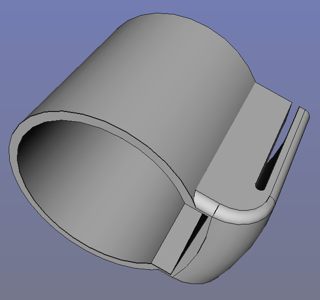
The boxes for the VMC board The designs are made with Freecad and print in PLA. The files are allow on account Github: https://github.com/InnoGreenTech
|