|
Electronic cards for solar greenhouse.
|
|||||||||||||||||||||||||||||||||||||||||||||||||||
|
The control cards of the connected solar greenhouse are ready. They are going to allow to manage and monitor the greenhouse, the composter and the garden. They allow to connect a lot sensors and actuators. Of course you will able to use them for another applications. My green house is small, but you can use them on a application bigger. My but is to develop intelligent softwares that will be able to adapte themselves at their environmental. If for me the connectivity is important to analysis the datas, it is not essential, the system can work without, the system need able to work in autonomy, without wireless connection.
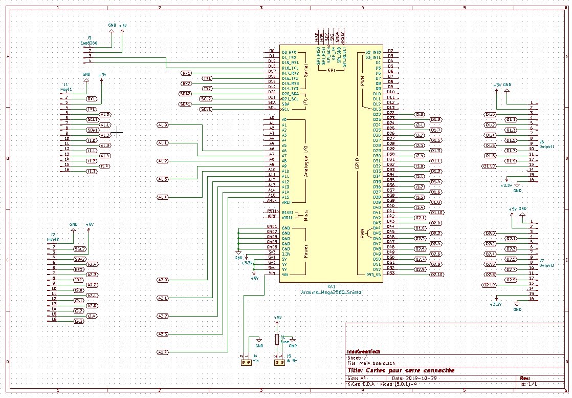
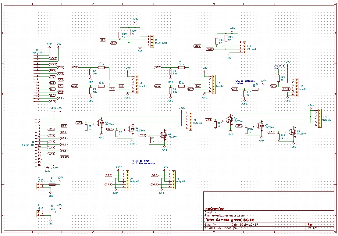
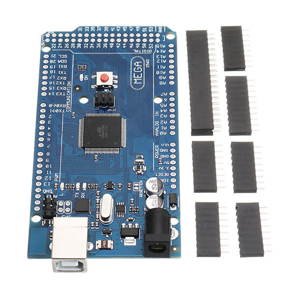
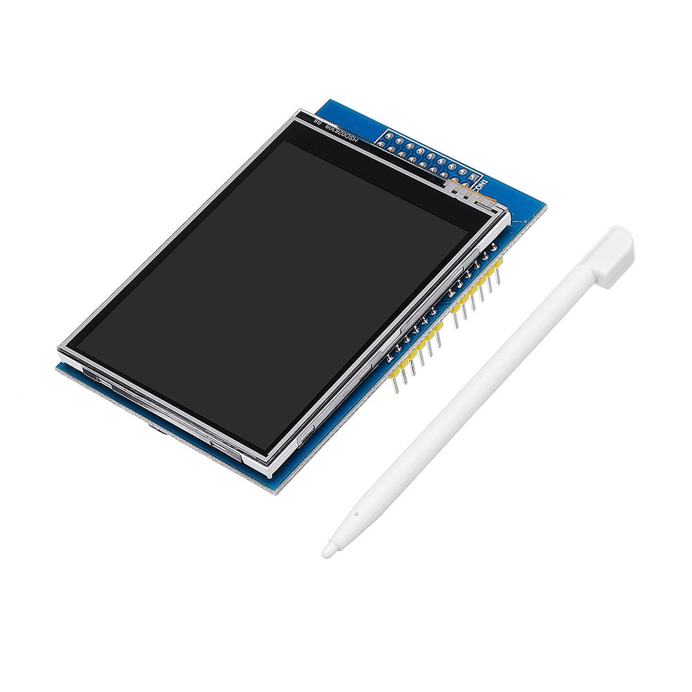
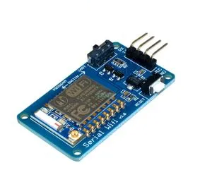
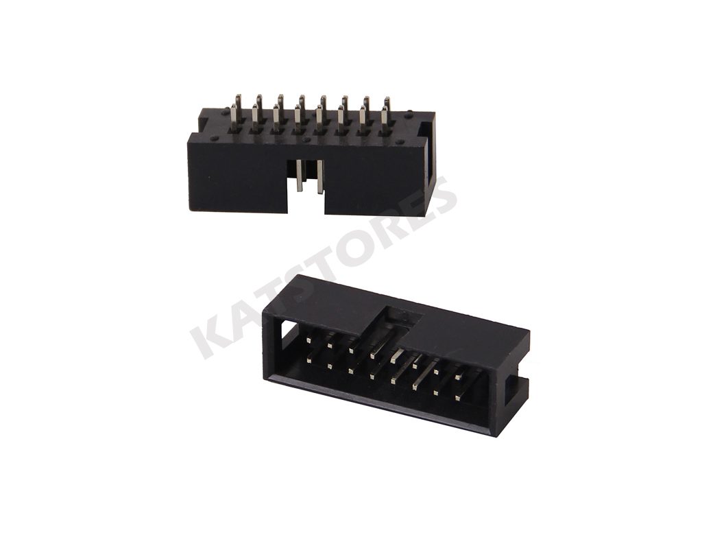
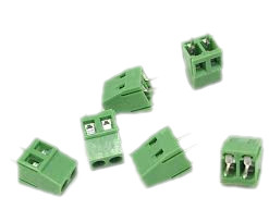
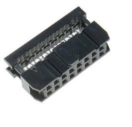
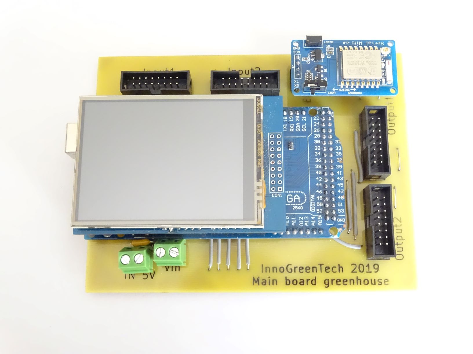
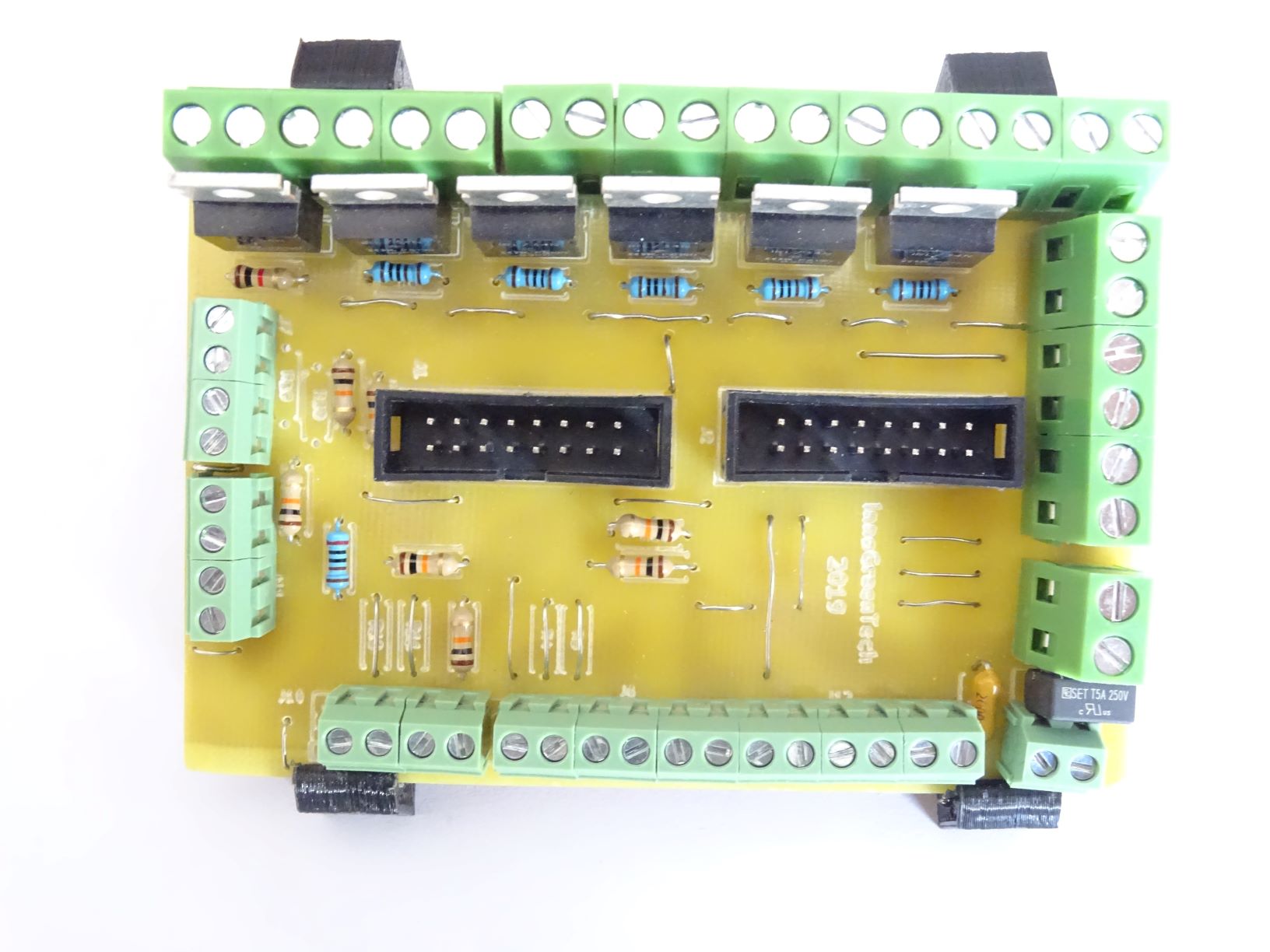
The set consists of main board make around a Arduino méga, a touch screen and a ESP8266 for the connectivity (optional). There are also two slave cards where it will be possible to connect many sensors and actuators by screw terminal blocs. Each slave board have: -4 analog inputs with locations to put resistors to make voltage divisor bridge. -1 analog input to control the voltage of the batterie ( able to read 0 à 30 volts). -4 inputs TOR 5 volts -1 bus OneWire -6 outputs connected at a mosfet able to switch 30 amp -4 outputs 5 volts to pilote step motors or servo motors -1 output 5 volts -1 serial port -1 I²C port Behind of this article i will accompany you land give you whole information to make those boards. In another article i will introduce to you the software of the main board. I have already worked on it. To finance and support my projects i will sent starting sets to help you to create your own controller. Of course at the end of this article you will able to make your cards this project is open. I hope that someone will made it.
Important you will able to found update information : https://github.com/InnoGreenTech/Solar-connected-greenhouse
|
|||||||||||||||||||||||||||||||||||||||||||||||||||
|
Summary
1-Electric drawings 3-PCB cards 3-Card holder
|
|||||||||||||||||||||||||||||||||||||||||||||||||||
|
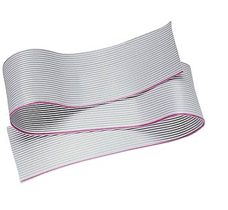
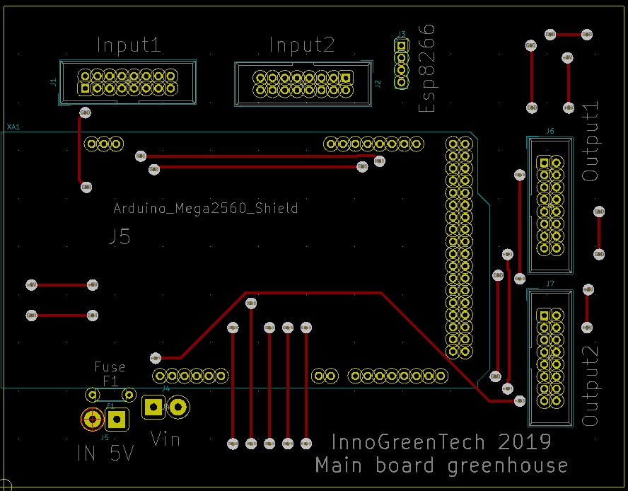
1-Electric drawings: I have made my drawings with Kicad. Kicad is a open source software, it is great, support by a large community. I have created three electronic drawings these are going to able to exploit at best the capacities of the Arduino mega. and control the solar greenhouse , the lombric-compost and the garden. The main board of the connected solar greenhouse have a Arduino mega, a sensitive tft screen and a optional ESP8266 to catch datas and share them on the web. Four connectors with 16 pins allow to connect the inputs and outputs at two slave cards.
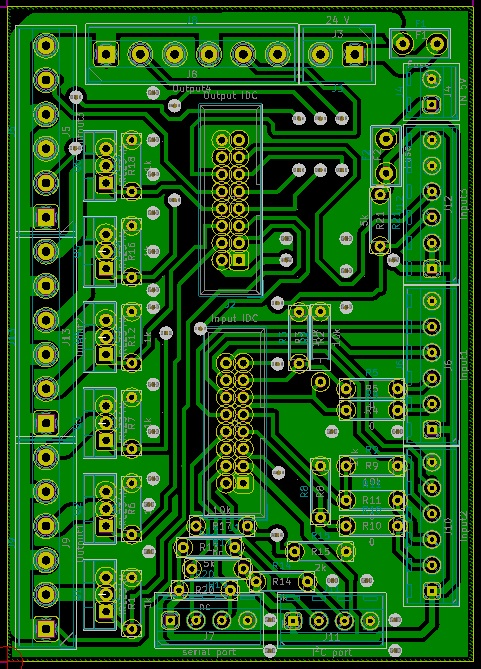
The remote module for the technical room will allow to control the automatic spray, the lombric-composter and the garden. There are six Mosfet to power actuator like pumps, fan, heater. Also there are to connector for stepper-motors or servo-motors. I will use them for shutter for example. The last card is for the greenhous, it will control the cooling system, the ventilation, the horticole light, heater of soil,....It is the same drawing. You can download Kicad files here les fichiers.
|
|||||||||||||||||||||||||||||||||||||||||||||||||||
|
2-Parts list:
|
|||||||||||||||||||||||||||||||||||||||||||||||||||
3-PCB cards: Here too, i have used KiCad software. It optimize for a single face copper, it is possible to use it for double face copper, like this you can win a little bit time. To create the PCB of the main board you need a plate of copper of 150x100 mm. To win place for the tracks i have not uses every pads of the footprints of the arduino méga. So it is necessary to adapt new connectors on the arduino mega. I have updated the PCB since the picture, i have changed the footprints of fuse and terminal blocs.
To make the PCB of both remote cards of the connected solar greenhouse, you can use only a copper plate of 100x150. Here too i tried to optimise the tracks. Since the picture i have updated the PB to add a resistor for a OnwireBus and to adjust the step of the sensor terminals.
|
|||||||||||||||||||||||||||||||||||||||||||||||||||
|
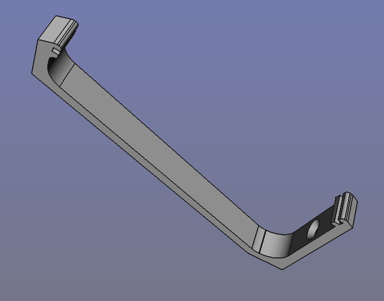
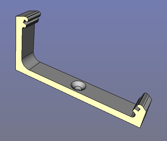
4-Card holders: With Freecad I have create holders for my boards. They are very simple, it will be necessary to to protect them. For the main card i use three holders
And two holders by remote cards.
|
|||||||||||||||||||||||||||||||||||||||||||||||||||